One-Piece Desktop Phone Stand 3D-Printable Model
A sky-blue, one-piece phone stand with a triangular support, twin hooks and a charging-cable opening. Orbit the model to inspect its rounded, printable structure. Generated by Kimi K3.1 Pro.
Loading preview...
Start from this prompt
A sky-blue, one-piece phone stand with a triangular support, twin hooks and a charging-cable opening.
Try 3D MakeCreate a one-piece desktop phone stand suitable for 3D printing, with a clean, rounded appearance and a matte sky-blue plastic finish. The stand should consist of a horizontal base, an inclined phone backrest, and a rear support panel. Viewed from the side, these components should form a stable triangular structure. The design must have no hinges, screws, or moving parts. The base should be a rounded rectangular plate approximately 90 mm wide, 100 mm deep, and 5 mm thick, with rounded corners and smoothly filleted edges. The overall height of the stand should be approximately 110 mm. The phone backrest should be approximately 85 mm wide and inclined at an angle of approximately 65° relative to the desktop surface. Its front face should be flat and smooth to support the back of the phone. At the top, the backrest should transition through a smooth curved bend into the rear support panel. The rear support panel should extend downward and backward, merging seamlessly with the rear edge of the base. A large rounded triangular cutout should be incorporated into the center of the rear support panel. Maintain a structural border of at least 10 mm around the cutout. The lower edge of the backrest should be suspended approximately 25 mm above the base. Two support hooks, each approximately 25 mm wide, should be positioned on the left and right sides. Each hook should project forward from the backrest and curve upward at its outer end, forming a cradle for the bottom edge of the phone. The cradle should have a clear internal depth of approximately 14 mm, with a front retaining lip approximately 10 mm high, allowing it to accommodate a phone with a protective case. Use continuous curved transitions between the hooks and the backrest, giving the hooks a thick, smooth, and rounded profile. Leave a central U-shaped opening approximately 25 mm wide between the two support hooks to provide clearance for a charging connector and cable. Keep the front surface of the backrest clean and minimal, with no text, logos, or decorative markings. Use 5 mm as the nominal wall/plate thickness throughout the design. Connection areas should be appropriately thickened and reinforced with generous fillets to ensure sufficient structural strength. All exposed edges should be rounded to eliminate sharp corners. The dimensions above are intended as initial design values and may be adjusted slightly where necessary for structural integrity and printability. Make the following dimensions parametric and adjustable: overall width, overall height, base depth, plate thickness, backrest inclination angle, and support-hook dimensions. The final model must be a single connected, watertight, manifold solid with no self-intersections, suitable for 3D printing.
Add touch controls
Adds phone controls and layout without changing the other requirements.
Try 3D MakeCreate a one-piece desktop phone stand suitable for 3D printing, with a clean, rounded appearance and a matte sky-blue plastic finish. The stand should consist of a horizontal base, an inclined phone backrest, and a rear support panel. Viewed from the side, these components should form a stable triangular structure. The design must have no hinges, screws, or moving parts. The base should be a rounded rectangular plate approximately 90 mm wide, 100 mm deep, and 5 mm thick, with rounded corners and smoothly filleted edges. The overall height of the stand should be approximately 110 mm. The phone backrest should be approximately 85 mm wide and inclined at an angle of approximately 65° relative to the desktop surface. Its front face should be flat and smooth to support the back of the phone. At the top, the backrest should transition through a smooth curved bend into the rear support panel. The rear support panel should extend downward and backward, merging seamlessly with the rear edge of the base. A large rounded triangular cutout should be incorporated into the center of the rear support panel. Maintain a structural border of at least 10 mm around the cutout. The lower edge of the backrest should be suspended approximately 25 mm above the base. Two support hooks, each approximately 25 mm wide, should be positioned on the left and right sides. Each hook should project forward from the backrest and curve upward at its outer end, forming a cradle for the bottom edge of the phone. The cradle should have a clear internal depth of approximately 14 mm, with a front retaining lip approximately 10 mm high, allowing it to accommodate a phone with a protective case. Use continuous curved transitions between the hooks and the backrest, giving the hooks a thick, smooth, and rounded profile. Leave a central U-shaped opening approximately 25 mm wide between the two support hooks to provide clearance for a charging connector and cable. Keep the front surface of the backrest clean and minimal, with no text, logos, or decorative markings. Use 5 mm as the nominal wall/plate thickness throughout the design. Connection areas should be appropriately thickened and reinforced with generous fillets to ensure sufficient structural strength. All exposed edges should be rounded to eliminate sharp corners. The dimensions above are intended as initial design values and may be adjusted slightly where necessary for structural integrity and printability. Make the following dimensions parametric and adjustable: overall width, overall height, base depth, plate thickness, backrest inclination angle, and support-hook dimensions. The final model must be a single connected, watertight, manifold solid with no self-intersections, suitable for 3D printing.
Create a one-piece desktop phone stand suitable for 3D printing, with a clean, rounded appearance and a matte sky-blue plastic finish. The stand should consist of a horizontal base, an inclined phone backrest, and a rear support panel. Viewed from the side, these components should form a stable triangular structure. The design must have no hinges, screws, or moving parts.
The base should be a rounded rectangular plate approximately 90 mm wide, 100 mm deep, and 5 mm thick, with rounded corners and smoothly filleted edges. The overall height of the stand should be approximately 110 mm.
The phone backrest should be approximately 85 mm wide and inclined at an angle of approximately 65° relative to the desktop surface. Its front face should be flat and smooth to support the back of the phone. At the top, the backrest should transition through a smooth curved bend into the rear support panel. The rear support panel should extend downward and backward, merging seamlessly with the rear edge of the base.
A large rounded triangular cutout should be incorporated into the center of the rear support panel. Maintain a structural border of at least 10 mm around the cutout.
The lower edge of the backrest should be suspended approximately 25 mm above the base. Two support hooks, each approximately 25 mm wide, should be positioned on the left and right sides. Each hook should project forward from the backrest and curve upward at its outer end, forming a cradle for the bottom edge of the phone.
The cradle should have a clear internal depth of approximately 14 mm, with a front retaining lip approximately 10 mm high, allowing it to accommodate a phone with a protective case. Use continuous curved transitions between the hooks and the backrest, giving the hooks a thick, smooth, and rounded profile.
Leave a central U-shaped opening approximately 25 mm wide between the two support hooks to provide clearance for a charging connector and cable. Keep the front surface of the backrest clean and minimal, with no text, logos, or decorative markings.
Use 5 mm as the nominal wall/plate thickness throughout the design. Connection areas should be appropriately thickened and reinforced with generous fillets to ensure sufficient structural strength. All exposed edges should be rounded to eliminate sharp corners.
The dimensions above are intended as initial design values and may be adjusted slightly where necessary for structural integrity and printability. Make the following dimensions parametric and adjustable: overall width, overall height, base depth, plate thickness, backrest inclination angle, and support-hook dimensions.
The final model must be a single connected, watertight, manifold solid with no self-intersections, suitable for 3D printing.
You Might Also Like
Portable Folding Hanger 3D-Printable Model
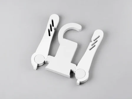
A portable gray hanger with a hook and two arms joined by print-in-place pivots. Inspect how the arms open to support clothing and fold into a compact strip. Generated by Kimi K3.1 Pro.
Pocket Field Palette 3D-Printable Model
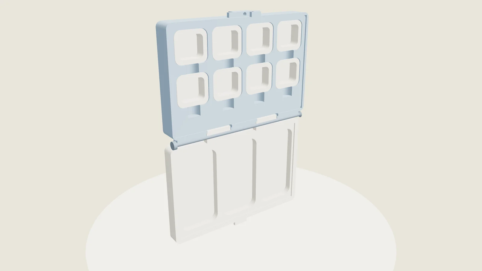
A folding watercolor palette with eight removable paint trays, three mixing wells and a removable hinge pin. Open, closed and exploded views show its assembly. Generated by Kimi K3.1 Pro.